Connecting RC522 with ESP32
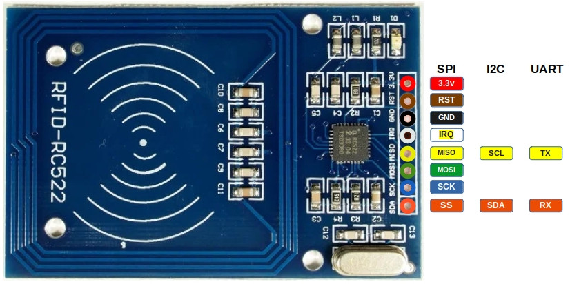
Pinout diagram of RC522
There are 8 pins in the RC522 RFID module.

| Pin | SPI Function | I²C Function | UART Function | Description |
|---|---|---|---|---|
| 3.3V | Power | Power | Power | Power supply (3.3V). |
| GND | Ground | Ground | Ground | Ground connection. |
| RST | Reset | Reset | Reset | Reset the module. |
| IRQ | Interrupt (optional) | Interrupt (optional) | Interrupt (optional) | Interrupt Request (IRQ) informs the microcontroller when an RFID tag is detected. Without using IRQ, the microcontroller would need to constantly poll the module. |
| MISO | Master-In-Slave-Out | SCL | TX | In SPI mode, it acts as Master-In-Slave-Out (MISO). In I²C mode, it functions as the clock line (SCL). In UART mode, it acts as the transmit pin (TX). |
| MOSI | Master-Out-Slave-In | - | - | In SPI mode, it acts as Master-Out-Slave-In (MOSI). |
| SCK | Serial Clock | - | - | In SPI mode, it acts as the clock line that synchronizes data transfer. |
| SDA | CS (or SS) | SDA | RX | In SPI mode, it acts as the Chip select (CS, also referred as Slave Select). In I²C mode, it serves as the data line (SDA). In UART mode, it acts as the receive pin (RX). |
Connecting the RFID Reader to the ESP32
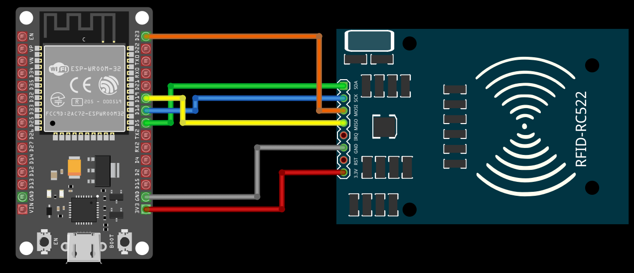
To establish communication between the ESP32 and the RFID Reader, we will use the SPI (Serial Peripheral Interface) protocol. The SPI interface can handle data speed up to 10 Mbit/s. We wont be utilizing the following Pins: RST, IRQ at the moment.
| ESP32 Pin | Wire | RFID Reader Pin |
|---|---|---|
| 3.3V |
|
3.3V |
| GND |
|
GND |
| GPIO 5 |
|
Labeled as SDA, it acts as the CS pin when using SPI. |
| GPIO 18 |
|
SCK |
| GPIO 19 |
|
MISO |
| GPIO 23 |
|
MOSI |
