Voltage Divider
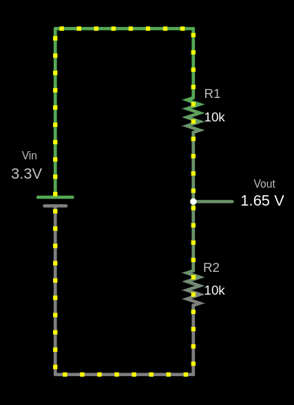
A voltage divider is a simple circuit that reduces an input voltage \( V_{in} \) to a lower output voltage \( V_{out} \) using two series resistors. The resistor connected to the input voltage \( V_{in} \) is called \( R_{1} \), and the other resistor is \( R_{2} \). The output voltage \( V_{out} \) is taken from the junction between \( R_{1} \) and \( R_{2} \), producing a fraction of \( V_{in} \).
Circuit

The output voltage (Vout) is calculated using this formula:
\[ V_{out} = V_{in} \times \frac{R_2}{R_1 + R_2} \]
Example Calculation for \( V_{out} \)
Given:
- \( V_{in} = 3.3V \)
- \( R_1 = 10 k\Omega \)
- \( R_2 = 10 k\Omega \)
Substitute the values:
\[ V_{out} = 3.3V \times \frac{10 k\Omega}{10 k\Omega + 10 k\Omega} = 3.3V \times \frac{10}{20} = 3.3V \times 0.5 = 1.65V \]
The output voltage \( V_{out} \) is 1.65V.
fn main() {
    // You can edit the code
    // You can modify values and run the code
    let vin: f64 = 3.3;
    let r1: f64 = 10000.0;
    let r2: f64 = 10000.0;

    let vout = vin * (r2 / (r1 + r2));

    println!("The output voltage Vout is: {:.2} V", vout);
}
Use cases
Voltage dividers are used in applications like potentiometers, where the resistance changes as the knob is rotated, adjusting the output voltage. They are also used to measure resistive sensors such as light sensors and thermistors, where a known voltage is applied, and the microcontroller reads the voltage at the center node to determine sensor values like temperature.
Voltage Divider Simulation
Formula: Vout = Vin × (R2 / (R1 + R2))
Filled Formula: Vout = 3.3 × (10000 / (10000 + 10000))
Output Voltage (Vout): 1.65 V
Simulator in Falstad website
I used the website https://www.falstad.com/circuit/ to create the diagram. It's a great tool for drawing circuits. You can download the file I created, voltage-divider.circuitjs.txt, and import it to experiment with the circuit.